Now it’s time to make the pinhole. For this I followed the methods described by SROYON on the 35mmc website ( https://www.35mmc.com/26/10/2020/making-measuring-and-testing-the-optimal-pinhole-pinhole-adventures-part-3-by-sroyon/). This is well worth a read as it explains a lot about how to decide what size pinhole to use, how to make them and various ways of measuring them. I’m not going to go into any of that since I can’t explain it any better. I’m just going to tell you what I did.
For the material for the pinhole I used the aluminium from a small soft drink can, it’s easy to cut with either scissors or a Stanley knife. I then used a fairly fine sewing needle to make the hole. I ideally wanted to get a pinhole diameter of 0.47mm which according to the theory would give optimum resolution for my focal length (100mm). I chose to go for maximum resolution rather than maximum contrast (see article above) as this would also give me a slightly lower f number, in my case a pinhole of 0.47mm would be f213.
I made four pinholes at a time using the method described in the SROYON article and went cautiously so as not to made too big a pinhole right from the start. I then measured the size of the pinholes four at a time to save scanning time.
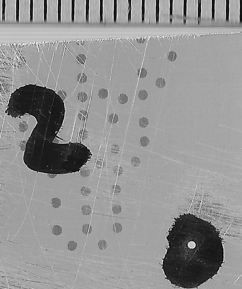
In order to measure the size of the pinholes I used a marker pen to blacken around the pinholes and then scanned them next to a mm ruler at the maximum resolution of the scanner (1200dpi). I then cropped the scans as tight as I could whilst still including both the pinhole and the ruler in the image, see example below. Note the halo effect around the black of the marker pen and on the inside of the pinhole. I suspect this is a scanning artifact (excessive sharpening) so I ignored it and counted it as part of the hole.
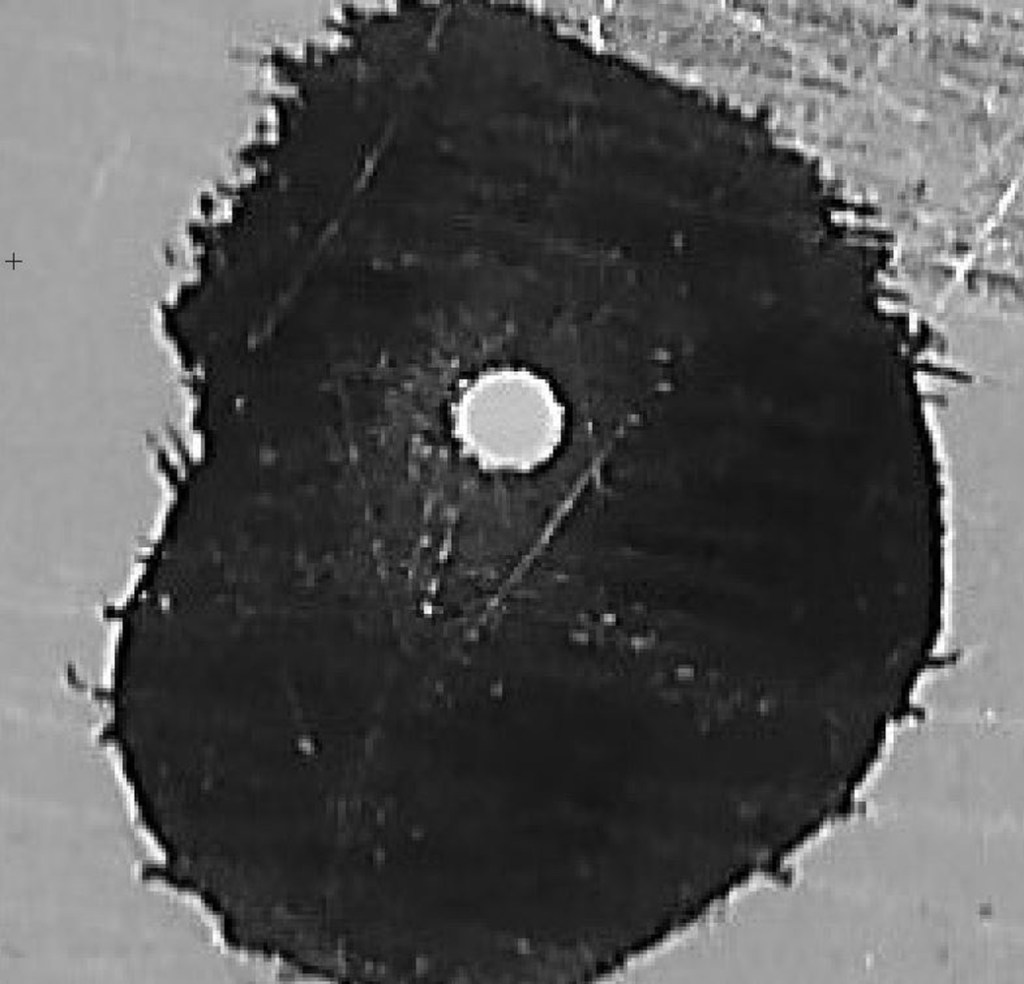
I then enlarged this in Photoshop and while at maximum scale (1600%) measured the diameter of the hole ‘on screen’ with a ruler and then measured 1mm of the ruler scale again ‘on screen’. Dividing one by the other gave me the diameter of the hole.
For the pinhole I finally settled on, I measured the diameter of the hole to be (100±1mm) and the 1mm on scale of the ruler to be (203±1mm). Dividing one by the other I get a diameter of 0.49mm. I can only guess at the accuracy of this result but I would hope it is ± 5% which is ± 0.01mm. Close enough to the ideal diameter of 0.47mm that I was looking for and at a focal length of 100mm this means my aperture is f204.
It had taken me three attempts making four pinholes at a time, that is twelve in all, before I had made one close enough to the size I wanted.
The pinhole was mounted onto the large steel washer with double sided sticky tape and secured with more black tape, leaving the pinhole uncovered of course and then any shiny surfaces were blackened either with black paint or marker pen.
All of the internal surfaces of the three parts of the camera were then painted with two coats of matt black paint taking care to include the insides of the light traps and the ends of the centre box.
Now for the final assembly.
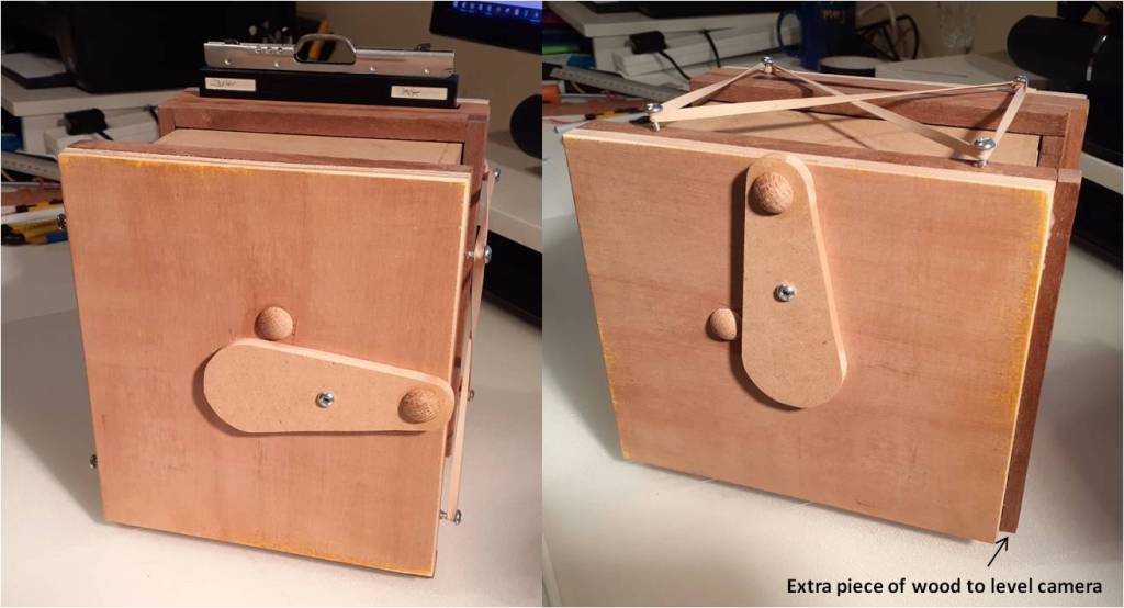
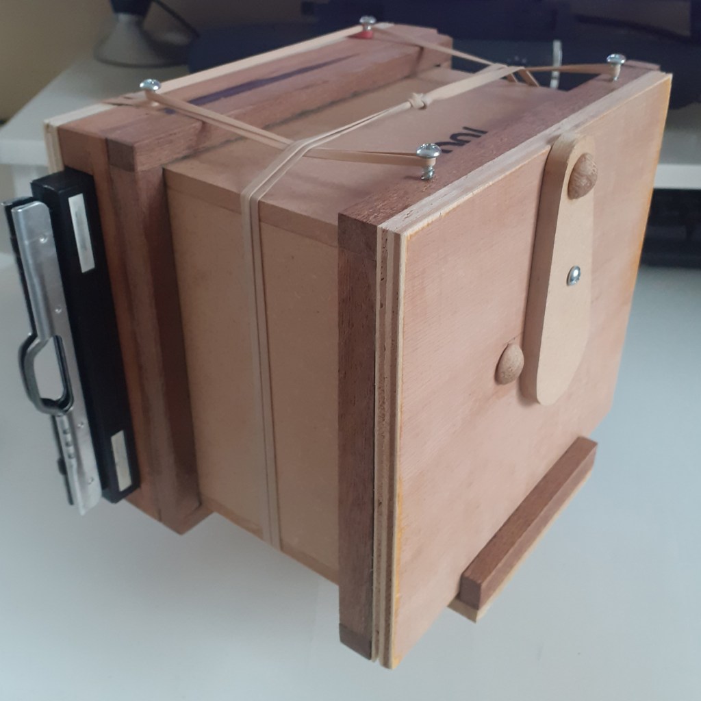
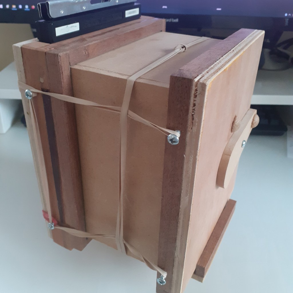
Small screws were fitted to the top and bottom of the backplate 30mm in from the edges, and similarly screws were fitted to the front plate to line up. It was here I realised that I need to add a small piece of wood to the bottom of the front plate so that the camera would be level when I rotated it from landscape to portrait. Here’s a picture of the final camera (it might get a coat of varnish at some time to finish it off).
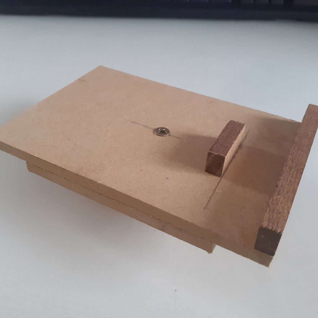
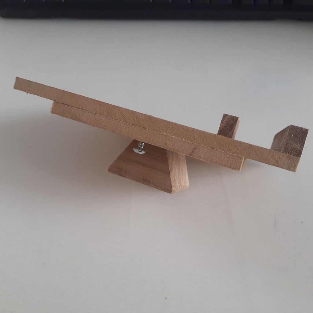
Finally I made an adaptor to allow me to mount the pinhole camera onto a tripod. It has a block of wood shaped to fit the quick release of the tripod and a platform on which to place the camera with wooden ridges to stop the camera sliding backwards or forwards. This a such that the camera can be mounted portrait or landscape. The camera is then held on to the mount with (you’ve guessed it) rubber bands, nothing high tech here.
Now I need to get some film or paper and try it out.
